
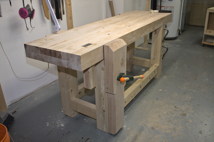
Figure 1: My Workbench
I have been doing woodworking at a very slow pace for about three years or so. I am retired, old, and so I don’t move very fast. My original intention was to build various musical instruments, including electric guitars.
I built a workbench using the design presented in Chris Schwarz’ book The Anarchist’s Workbench. This was the longest, most challenging project I have undertaken in my short time doing woodwork. I purchased the materials in late summer of 2020. The project bogged down for various reasons, including my health problems, and the fact that I have to work without anyone’s help, especially during the covid-19 lockdowns.
Perhaps this blog entry will be useful to other beginning woodworkers who intend to build a workbench. I am not going to make any attempt to shorten up this blog entry. Feel free to skip ahead or skip it altogether if it’s too long for you.
Note: I am in Ontario. I am sorry to say that we are stuck with Imperial units for woodworking, so I’ll list dimensions accordingly.
The Workbench
Some basic details of the design:
- The top is 22 inches wide by 77.5 inches long. It is 4.375 inches thick, and is constructed of hard maple. More on that below.
- The overall height is 33.5 inches. I’m short; the top edge of the bench comes exactly to my wrist joint.
- The leg vise is also hard maple, 3 inches thick. I used a Benchcrafted Criss-Cross for the leg vise, and a screw mechanism purchased at Busy Bee Tools here in Ontario.
- The undercarriage is made of big box store construction lumber. Here in Ontario, Southern Yellow Pine (recommended by Schwarz) is not readily available. Home Depot designates their softwood construction lumber “SPF” (for spruce-pine-fir). I hate working with this stuff. More on that below.
Here are more photos:
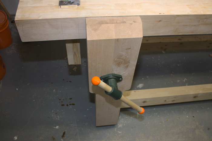
Figure 2: The Laminated Maple Leg Vise
Leg vise from the side, with the Benchcrafted Criss-Cross. I made those colourful orange knobs on my 3D printer:
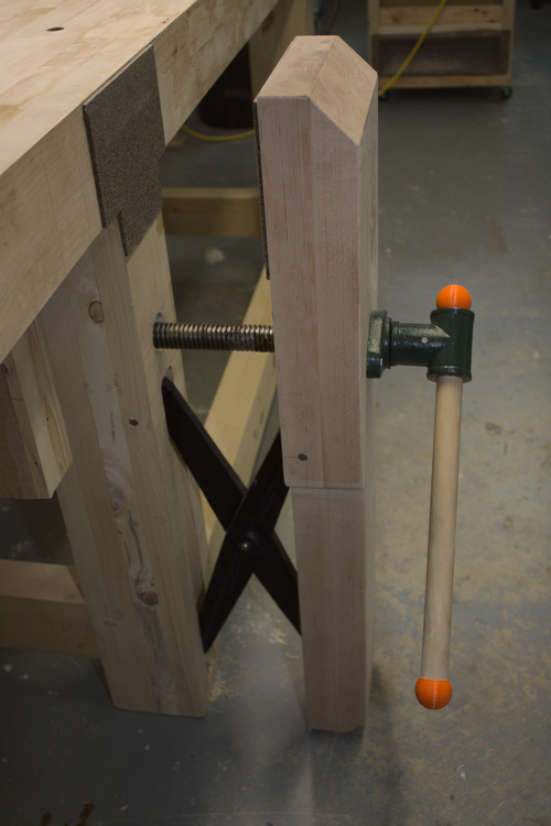
Figure 3: Leg Vise Hardware
Holdfasts are great:
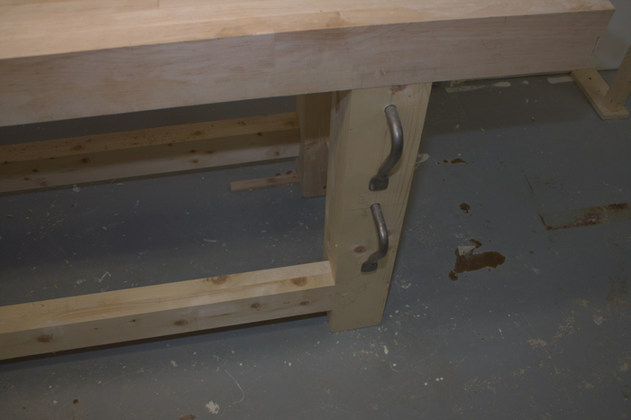
Figure 4: Holdfasts Stored in a Leg
The History
For the first years of my attempts at woodworking I had been using a rickety old workbench that I made from plywood and some 4×4 fence posts. I got quite a bit done with that old thing, but it was frustrating in many ways. The work-holding was poor. I installed a Lee Valley front vise on it, which worked reasonably well. But the bench was too light, and not very rigid. Whenever I did any heavy hand planing, the bench would skate across the floor, and had to be dragged back into its spot every ten minutes or so. The height was wrong.
When I first started woodworking, I was inspired by Paul Sellers’ videos. I decided to make a workbench by following Sellers’ series in which he make a bench in his back yard, or “garden” as Brits say. To that end I gradually purchased a bunch of long, light aluminum clamps similar to the ones Sellers uses in the videos. But, I didn’t get around to building a bench for a long time.
In the meanwhile, I had started watching other woodworking channels on YouTube. I soon realized that Paul Sellers channel, although inspiring and informative, didn’t really have all that much to do with the projects I intended to tackle. I eventually purchased one of Chris Schwarz’ earlier books on workbenches. I found his opinions on bench design compelling, and decided on a design from The Anarchist’s Workbench.
Choice of Material for the Top
I decided to use hard maple for the top. This decision was based on my dislike for “SPF” construction lumber, and a bit of impractical romantic attraction to hard maple.
A local family-run lumberyard carries what they call “brown hard maple” at a very good price. I had used this wood for a couple of other projects (wooden bench planes, for example). It is a joy to work with, and has a fair bit of character in appearance. I has the odd brown streak here and there, which the lumber yard owner calls “sugar streaks”. It came rough, of course, so jointing, planing and dimensioning were required. This created some challenges for me.
The lumber yard had a selection of 8/4 boards that were between 9″ and 10″ wide. Most were about 8′ long, but many had quite a lot of wane, and some splitting on the ends. I quickly realized that I would be unable to achieve the full thickness of 5″ recommended by Schwarz without wasting a huge amount of maple. The length also posed something of a problem, which I’ll describe.
Anyway, I purchased what I thought was a sufficient quantity of maple for the top, and 2×12 construction lumber for the undercarriage. I let the lumber acclimatize in my basement for six weeks or so, and got to work.
Milling the Maple
Here is where I ran into some trouble.
The first step, which went well, was to rip the boards down the middle using my 14″ band saw. The rough boards were all cupped enough to make them extremely hazardous to rip on the table saw.
The next step was jointing the boards, which were now mostly just shy of 5″ wide. This was difficult. At the time I had an old Busy Bee jointer, made in about 1985. Here it is:
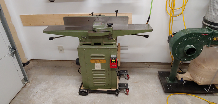
Figure 5: My Old Jointer
The jointer worked alright, but I had a lot of trouble setting it up to avoid snipe, and to keep the knives even. I have since come to realize that I was setting up the knives and outfeed table wrong. (I won’t bother describing my mistake!)
Despite the limitations of the old jointer, I got two faces of all my maple boards jointed reasonably well. A little too much snipe on the trailing end, but oh well.
The real problem came when I ran the boards through my Ridgid thickness planer. I simply did not have enough support on either the infeed or the outfeed side. This created problems greater than just snipe. The heavy maple boards bounced or oscillated a little vertically on the way through the planer. This caused some of them to be fairly severely scalloped, and necessarily caused the loss of some thickness when cleaned up.
So, at that point I felt somewhat discouraged. I had run into problems squaring up individual boards. What would happen when I had to mill up beams of several boards laminated together?
On top of the poor results thickness planing the boards, I had also foolishly done the jointing without wearing my respirator mask. My faulty reasoning was that the jointer produced ribbons or slivers of wood rather than fine sawdust, so…duh…I should be OK. NOT.
I ended up with very a nasty respiratory inflammation that kept my away from woodworking for six weeks. I posted a long story on Rex Krueger’s forum about this, and got a lot of feedback on how dangerous wood dust can be. I ended seeing a respiratory specialist, got a lung MRI, and so on. But that is another story. Suffice it to say that I do nothing that creates dust without wearing a respirator mask. And, when working in the garage, I open doors at both ends to move tiny particles out.
When I got feeling better, I decided to true up the boards by planing them by hand. This worked pretty well. I have a Veritas low angle jack plane, and a shop made wooden jointer plane.
However, at that point I faced another minor quandary. The boards I had were just too short to make a bench the size I wanted. What to do?
In the end I decided to add another two feet or so by simply butt joining additional maple pieces on either end. Of course, I alternated these extensions to avoid creating a weak glue joint right across the width of the top. The way I went about this was to simply add the extensions in when gluing up beams of three boards (in thickness). The first two beams I glued up did not turn out so well. The short extension pieces sagged a bit, being held by nothing but glue, a couple extra clamps, and prayer. After that I got smart and invested in a cheap biscuit joiner to hold everything in place vertically. Because I was unwilling to fix the misaligned extensions by planing away more thickness, I ended up routing some channels in the beams and gluing in 1/4 inch thick “dutchmen”, or graving pieces to make the laminations and extensions level.
Here is a glued-up beam, squared up with hand planes:
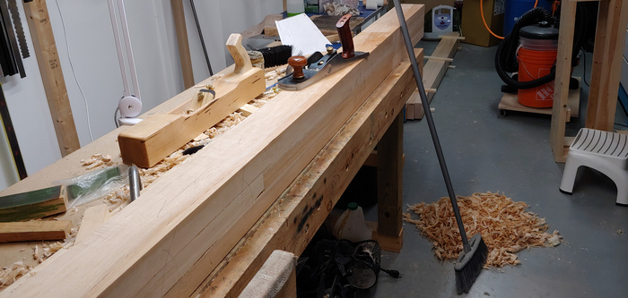
Figure 6: Squaring Up a Beam by Hand
And here is what the extension butt joints look like:
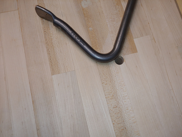
Figure 7: Extensions and Butt Joints
Undercarriage
I then turned my attention to the undercarriage. These, and the stretchers, are made from 2×12 construction lumber. This stuff is full of knots, and pockets of pitch. If I had it to do over again I probably would have used poplar. The knots created a couple of problems that I did not anticipate. I carelessly ended up with knots in the tenons of a couple of the legs, right smack on the edge of the location to be accurately drilled for the drawbore dowels. Also, chiselling a mortise through a hard-is-iron knot is no fun.
Here are some pictures of a leg:
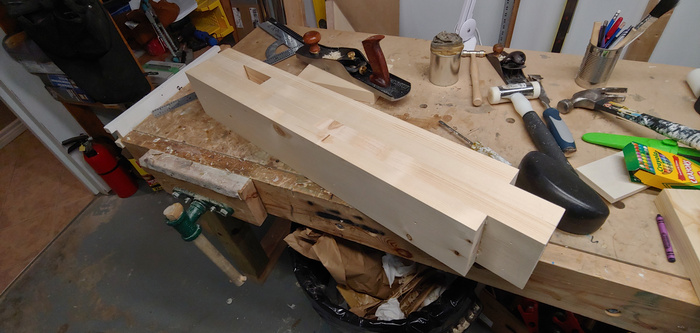
Figure 8: A Glued Up Leg
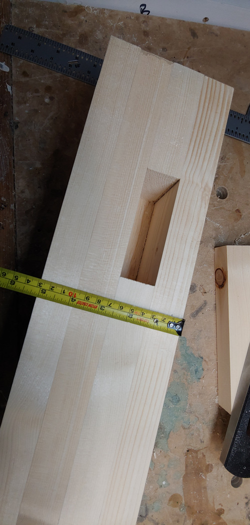
Figure 9: Leg Mortise for a Stretcher
Leg Vise
I also did a construction lumber mock-up of the leg vise. In the end I made the leg vise from hard maple. But I wanted to be sure that I understood how to rout the mortises for the Benchcrafted Criss-Cross accurately. The large holes for the vise screw had to be done accurately too. Here is the softwood mock-up:
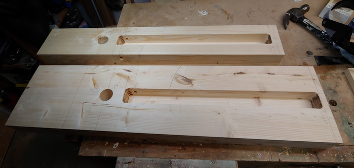
Figure 10: Leg Vise and Leg Mocked Up in Softwood
Now What?
So, by this point I had the undercarriage legs and stretchers made. And, I had four heavy maple beams to glue together to make the top.
Although I had done a pretty good job truing up the large beams with hand planes, dry fitting them revealed that they may not have been perfect enough to make tight glue joints. Pipe clamps did seem to squeeze them together adequately, but I just was not confident.
In The Anarchist’s Workbench, Chris Schwarz recommends running the beams for the top through the jointer and thickness planer again before the final glue-up. This, he suggests, is a two-person job. Those beams are heavy, and being hard maple, mine are really heavy. Given my bad experience jointing and planing single maple boards, and the potential to ruin several hundred dollars worth of hardwood after all that effort, I really got cold feet. I ended up doing nothing on the bench for at least six weeks.
Anyway, weary of fighting with the old jointer, I sold the beast of for a little more than I paid for it. (The covid-19 pandemic made used tools more attractive to a lot of people.) And, I broke open my piggy bank and bought a new jointer. I have not regretted the purchase. The fence is about an inch taller than the old one, and the outfeed table is adjusted by a hand wheel instead of a lever. Most important (to me) is the fact that knife height is adjusted by jack screws, not just springs. The overall design and construction are a big improvement over the old jointer. It made jointing the beams much easier. Here is a picture of the new jointer:
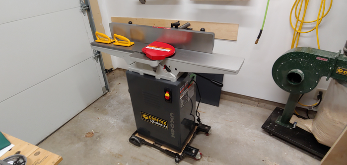
Figure 11: New Jointer
Final Jointing and Planing of the Maple Beams
The real challenge, though, was how to handle the heavy maple beams while jointing, and how to avoid the vertical bouncing when thickness planing. Since we were still in covid-19 lockdown, I considered it unwise to ask for help from a neighbour or friend. It eventually occurred to me that I could probably manage the beams while jointing if I added handles. So, for jointing the bottom faces, I added some drawer handles to the top of a beam to make pushing it across the jointer table steadily more reliable:
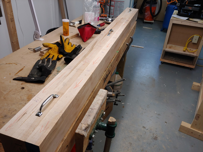
Figure 12: Drawer Handles Attached
This worked well. The more difficult part was jointing the next (adjacent) face. This required keeping the already jointed face pressed reliably against the fence, to keep things square. The solution was to drill 3/4″ holes in the opposite side of the face to be jointed, and insert (removable) dowels that would allow me to exert rotating force to keep the jointed face on the fence, while moving the beam through the jointer:
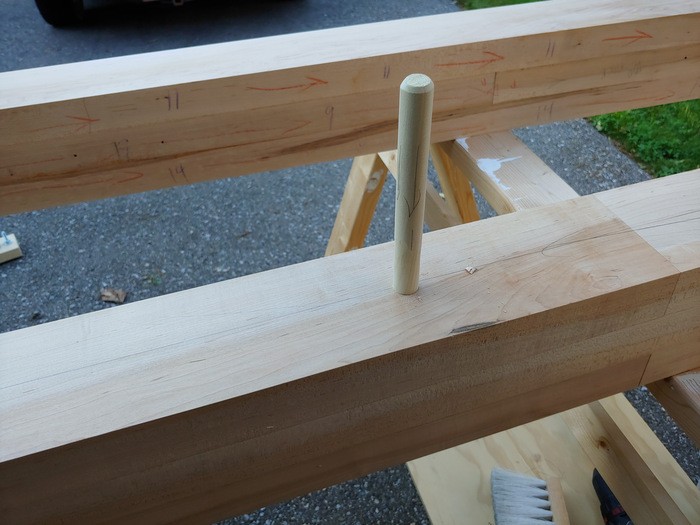
Figure 13: Dowel Handles Attached
This also worked very well. I was able to joint all four beams by myself.
The next step was thickness planing the other faces of the beams. I did what is now obvious to me, which is to use a long melamine board supported by roller stands:
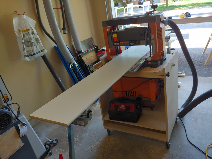
Figure 14: Proper Support for Planing
It worked! No scalloping, very little snipe! So now I had all of the beams squared up and ready to glue. Dry fitting the beams showed great promise: no visible gaps.
Gluing Up the Top
Final glue-up of the top went well. I did one glue joint at a time, once again with the help of biscuit joints to line up the beams:
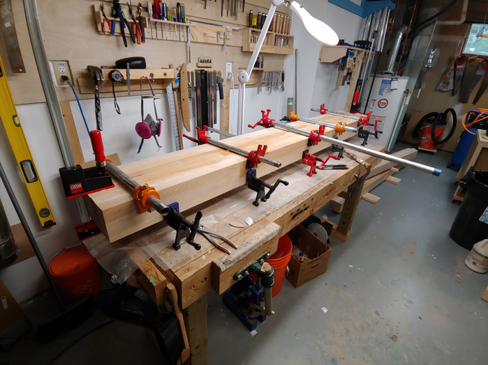
Figure 15: Two Beams Glued Up
I decided I wanted a slightly wider bench, so I added one more lamination, with four original beams making twelve layers, and the additional one making thirteen boards plus extension pieces:
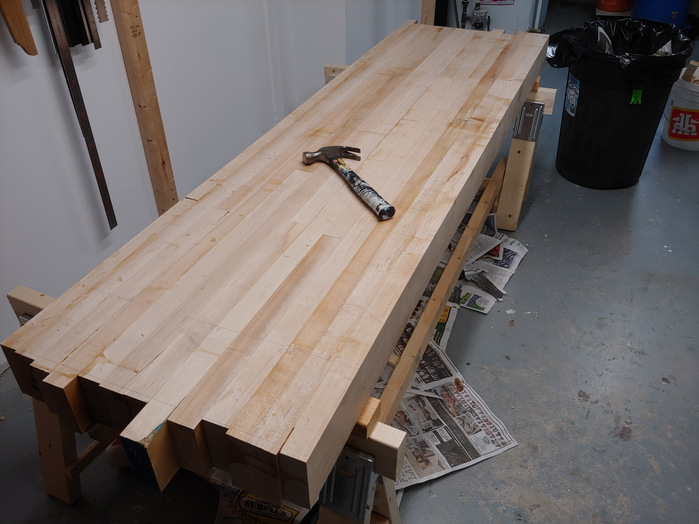
Figure 16: Entire Top Glued Up
Final Assembly
The next step was to cut the mortises in the underside of the maple top. The tenons in the legs fit into these. This was a bit nerve-wracking. It required dry fitting the undercarriage, and marking the mortise locations. Then, using a jig to keep the drill orthogonal, I hogged out most of the waste from the mortises. I used the superb Wood Owl bits for this. The task proved to be too much for my cordless drill, so I ended up buying a DeWalt corded drill with a 1/2″ chuck. Then I spent a long, long time chiselling the walls of the mortises to fit the tenons.
All of the mortise and tenon joints in this design are draw-bored. This allows one to dry fit the undercarriage to mark the tenons. Here is a picture of that step:
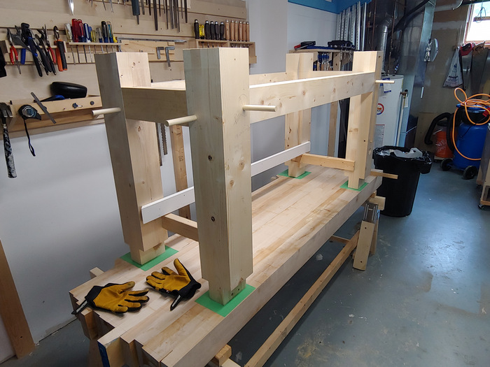
Figure 17: Marking Mortises with Assembled Undercarriage
So, with all of the mortises and tenons done, and the draw bore holes drilled, it was time to do the final assembly. Some hide glue on the tenons (as recommended by Chris Schwarz), fit everything together, and drive the draw bore dowels home. Here it is:
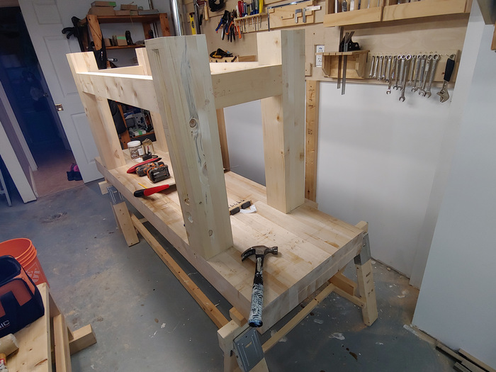
Figure 18: Assembled, Glued, Drawbored (Whew!)
At this point I breathed a big sigh of relief. All of the risky steps that could have ended in disaster, and ruined the bench, were completed successfully. It was now clear to me that I had succeeded!
Final installation of the leg vise and its hardware was a little fiddly, but went well.
By this time we were out of strict covid-19 lockdown, and I had received both of my vaccine jabs. So, I asked my neighbour to help me put the heavy, heavy bench on its feet.
I had already trimmed the ends of the top. I flattened the top with my hand planes. I used the bench in that state for about two months, and found it to be a real joy to work with.
Final Touches
However, I had not yet installed a planing stop, nor had I drilled dog holes. So the work holding aspect of the bench was incomplete.
Chris Schwarz’ design entails leaving a gap in the top laminations to create a mortise for the planing stop. Frankly, I just forgot to do that when constructing the top. I was so nervous about ruining all that hard maple that I just plain forgot this step. The implication was that I had to cut the mortise by hand, drilling out most of the waste and then chiselling the walls. This was not all that scary, because I recognized that I could cut the mortise first, and then fit the planing stop to it. So the mortise had to be square, but the dimensions were not critical.
There is one aspect of Chris Schwarz’ design that made no sense to me. That is, he uses a big ductile iron metal part in his planing stop. I recently noticed that he sells these. They are not cheap. I decided to fabricate my own, mimicking the design of the commercial Benchcrafted planing stop. (These cost about $50 at Lee Valley, but have been out of stock for some time.) Anyway, I made mine with $5 of material: a chunk of mild steel, a cross-dowel nut and a flat head socket screw. I ground an edge in the steel (like grinding a plane iron) and cut some teeth using a triangular file.
The planing stop and fastening hardware (no teeth yet):
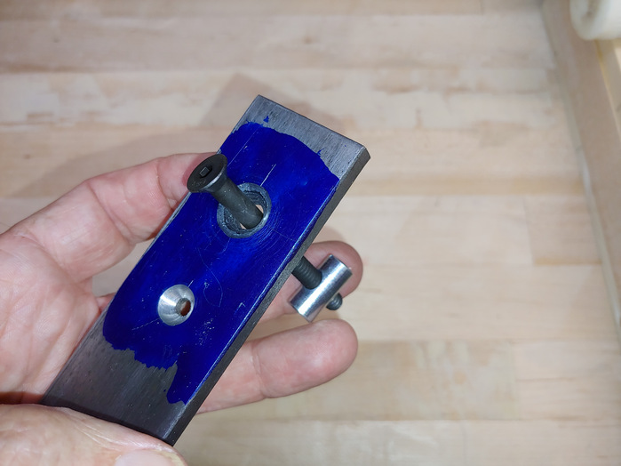
Figure 19: Shop Made Planing Stop In Progress
How the socket screw and cross dowel nut works:
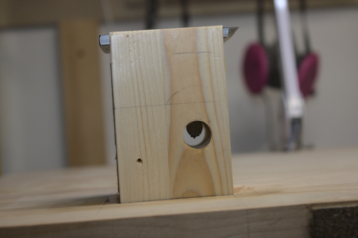
Figure 20: Planing Stop Attachment
The assembled planing stop moves up and down, and is held by friction in the mortise. Small clearance mortises in the top allow the metal stop to fit down flush in the bench top when not in use. This is another departure from Schwarz’ design.
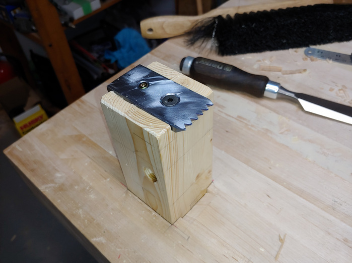
Figure 21: Completed Planing Stop
Finally, I drilled 3/4″ dog holes for bench dogs and holdfasts. I drilled these in the top in the pattern recommended in The Anarchist’s Workbench.
Conclusion
So, once again, here’s the finished bench. The white thing in the upper left corner is a movable LED lamp that fits neatly into dog holes. As I age, I need all the light I can get on the work.
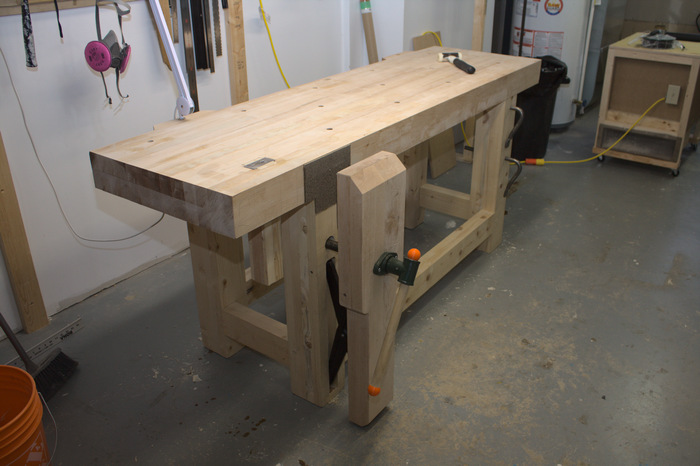
Figure 22: My Baby
Thanks for reading, if you made it this far through my lengthy saga. If I can do a project like this, so can you!